Tuesday, August 1, 2017

Altura - Load Tool Palette

If you have ever used AutoCAD, even if your level of experience was to open it and browse through its endless tools, then you know it is a very healthy program, abundant in applications and tools. The old saying, “There’s more than one way to skin a cat,” holds ever true with AutoCAD, where there is “more than one way to draw a line, and a circle, and a rectangle, and a helix...etc.”

To have such a myriad of choices at your fingertips, can be overwhelming for some and cause us to lose focus on the task at hand. Not only do you have to worry about completing a task, but you must figure out in what way will you complete it. To help, there is an Altura Tool Palette available which contains all the tools necessary to complete drawing tasks. A full functioning AutoCAD is still available, but the tool palette helps clear the clutter and directs you in one way.

Please watch...


Be Helpful,
Jeremy

Thursday, July 27, 2017

Altura - PTO Request

As much as we all love working here at Altura Engineering & Design, every now and then we must force ourselves, or maybe even be forced by our loved ones, to take a little time off. That’s why Altura has offered it’s full-time employees PTO, or Paid-Time Off. This way if the guilt of relaxing on the beach, when you should be clacking away on your office keyboard doesn’t quite do you in, then the guilt of receiving pay for relaxing on the beach when you should be clacking away on your office keyboard…will.
        
The world of engineering is filled to the brim with standards for all things, ensuring that its inhabitants do not cross the boundary into the darkness of self-thought and originality, so it only seems logical for there to be a standard for requesting PTO. Hence today’s acronym:
-TPPFRPTO-
“The Proper Procedure For Requesting Paid Time Off”

Please watch...


Tuesday, July 18, 2017

Cool Tips - Copy & Paste

If you do not know, you can use Windows shortcut keys for copy and paste (CTRL+C and CTRL +V) in AutoCAD as well as most other programs. For cad users though, we like to have the option of copying objects with a base point and pasting them with a base point, which is not available with these two keys.

However, if you use (CTRL + SHIFT + C) you are allowed to copy objects with a base point, and (CTRL + SHIFT + V) allows you to paste objects with a base point.

Be Helpful,
Jeremy

Wednesday, June 7, 2017

Pointsense Basic - Insert ReCap Point Cloud - A

To work with the Point Cloud inside AutoCAD, we make use of the Pointsense Plant software, also known as Kubit. This software is a pattern recognition program that identifies point patterns from the cloud, creates defined shapes from those patterns, then matches them with a pre-defined shape in the KPM database. This is how it "magically" creates pipe and steel shapes within AutoCAD.

To get started, you need to insert a Point Cloud into the AutoCAD model space. Begin with a fresh drawing, and select the "INSERT" button found in the Pointsense menu, Point Clouds area.


A browser window will open, navigate to the location of your point cloud file. For Altura designers, we use an RCP file, usually found in the Project Folder -> Project Drawings -> Recap. Select the file and pick  "OPEN/OK".

Another dialog box appears. This box allows you to set the Point Cloud Properties. The path should be "Absolute" and the Scan Units will always be "Meters". You can adjust the cloud's insert location by entering XYZ values. Most of the time they will be left ZERO. You need to make sure the Drawing Unit is set to "Inches (International)". This will allow you to work with the Point Cloud in Standard Units, while it stays in its native metric units.


After clicking okay, you may or may not see the point cloud. The cloud is not visible while in the "2D WIREFRAME" visibility setting. If it is not visible, then left click and change the visibility setting to "CONCEPTUAL".


Once the Point Cloud is visible, do a "RIGHT to LEFT" marquee selection drag across the cloud, right-click and select properties.


Notice in the properties box, there is a scale of "39.3701" and towards the bottom, the unit is set to "Meters". Remember when you inserted the Point Cloud, you left the scan units to "Meter" and the drawing units to "Inches (International)"? That is what you see here in properties. The original Point Cloud is in "Meters" and Autocad has applied the conversion scale factor so the drawing can be worked with in "Inches (International)". This is good information to know for troubleshooting when the point cloud KPM will not recognize properly.

The third item in the property box is the Locked item, which by default is "NO". Make sure you change this to "YES" by left clicking the "NO" and selecting "YES". This will lock the scan in model space, so you don' accidentally move it while working.

You should be set up now, to begin working with the Point Cloud in AutoCAD, making use of the Pointsense software. Please read this post, which will discuss setting up parameters to achieve good, pattern recognition fits.

Be Helpful,
Jeremy

Friday, May 5, 2017

Importing DXF File Into Staad Pro V8i

Before going through this exercise read through the CADWorx Midway - Model for Steel Analysis, STAAD blog post to understand how the model is created. This post is intended for designers and engineers to understand how to take models from CADWorx and import them into STAAD to be analyzed.

After the designer exports the dxf file open Staad Pro and click on the file menu->Import->3D DXF


Select the import button, then find the file that you want to import, select the file. Note, there may be an error that comes up after you import the file into Staad. To remedy this error save the dxf file on your local computer drive then import the file again. 

After importing the file, select all of the elements of the structure then select the geometry menu->Intersect Selected Members->Intersect. 


Then a box comes up that asks you to enter Tolerance put zero if it is not already selected. 


Then it will tell you if any new beams are created, click ok.


After this check to make sure that the stucture is all one and not broken up. Go to tools->Check Multiple Structures.


Now that you have a complete interconnected structure you can start defining the types of beams, loads, and supports that your project requires. In subsequent blog posts, I will show you how to apply and run an analysis from this point.  

Cheers,

Jonathan


Wednesday, April 12, 2017

CADWorx Midway - Model for Steel Analysis, STAAD

Most of the time the structural designs we contrive will need to be analysed by an engineer. Our in house engineer uses Bentley's STAAD analysis application, and I believe most of our clients do as well. We can model our structures in a way that requires no modifications by the engineer. This walk-through will be an example of proper modeling to achieve proper export and import.

A little understanding about STAAD. This application uses lines and nodes in order to make it's calculations. When it imports a model, it uses the center-lines of the steel we draw as it's reference.

So, the CADWorx Steel model center-lines are STAAD's lines, and the endpoints of the center-lines are STAAD's nodes.

In a previous post, I stressed that all structural models should be built with all center-lines connecting. This is why. STAAD uses the lines and endpoints as it's reference for calculations.

CADWorx Exported Model - SW 3D View
STAAD Imported Model - SW 3DView

Above you see the CADWorx model as exported out of CADWorx, and what the resulting import into STAAD looks like. Notice in STAAD all the lines (center-lines) are connected, because they are connected in the CADWorx model. The engineer does not need to modify the model in STAAD at this point. He can run his calculations. Here are some close-up pictures.

CADWorx Model Centerlines


STAAD Model Lines/Centerlines


CADWorx Model Centerlines
STAAD Model Lines/Centerlines
Notice in the pictures the correlation between the CADWorx Model center-lines and the STAAD model center-lines.

CADWorx Steel Modeling

Let's see how we can model to see that all center-lines connect.

Draw a W6x15 horizontal beam 10'-0" long. Notice the "Center-line Location" is at the TOP of the beam.


Next, see that your UCS is set to draw a vertical column (XY Plane), then place a W6x15 vertical column, with the "Center-line Location" in the CENTER location and the "Insertion Location" in the center. Select "Pick Points".

Snap to ENDPOINT of centerline,
using Polar Tracking, pull down and
enter 10', then select ENTER
Yes, the shapes are overlapping.

Move the vertical column to the right on the
X-axis 12", using polar tracking to keep you straight.
Yes the shapes are still overlapping.
It is important to use Polar Tracking or Orthogonal Tracking when moving shapes so the center-lines always stay connected. They were connected when you snapped to the ENDPOINT of the center-line. Alternatively, when you place other steel component, you can connect to the middle of a center-line by snapping to the MIDPOINT, or NEAREST of that line.

Now for the magical part, trimming the shape while keeping the center-line. For this use the CADWorx Steel COPE tool.


It will first ask you to select the object you wish to cope, or cut.


After this selection, push the ENTER key to accept. It then asks you to select the coping boundaries, which is the other object that will define how it copes (cuts) the first object you selected.


After this selection, push the ENTER key to accept. It will then ask if it is a BOLTED or WELDED type connection. We will select WELDED here. A welded connection will cope the steel flush with the connecting steel, while a bolted connection will leave 1/2" gap. In our designs, we do use both. Push the ENTER key to accept WELDED type.


And now you have a coped shaped, visually correct, with center-lines connecting for proper export/import with STAAD.


Now, try modelling the complete structure pictured at the beginning, using W6x15's and C4x5.4's for the angle pieces. Remember, those center-lines on the C4's must connect at the top as well. The trick is to use the CADWorx Steel COPE tool to modify the steel, rather than AutoCAD tools.

This holds true while working with CADWorx Steel components, DO NOT USE the AutoCAD ROTATE or MIRROR tools to modify the steel, you will run into placement issues later on. Instead double-click on the steel objects and use those placement tools to ROTATE or MIRROR you component.

Once you have the model complete, there are a few things you need to make sure you do: 
(-> equals ENTER)
  1. Set UCS to World coordinates. (UCS->W->), this will set the file to a Z-Axis up, which is needed by STAAD.
  2. Position the view as Southwest.
  3. Zoom Extents (Z->E->)
  4. Save
Finally, go to FILE and select SAVEAS. Browse to the Engineering Folder in your Project Folder, and find the STAAD Folder. Name your file appropriately, and make sure you change the file type from DWG to AutoCAD 2013, DXF.


There are a few things to note, when working on other structural designs. Since STAAD requires a DXF file, once you have the structure designed in your main working model, you will need to copy it from the original file, and paste it in a new file, so it is the only set of components in the file you send for analysis. Work with that file during the analysis until you receive engineering approval, then you can replace the original working model structure with the approved structure.

Also, depending on the complexity of the structural design, the several different types of shapes, and the several options of "Center-line Location" on each shape, you may want to work with the engineer during the modeling to make sure you are representing the steel properly with the center-lines, so STAAD will read it the way it should.

Please, feel free to to discuss any of this with me, or even Harder.

Be Helpful,
Jeremy

Tuesday, April 11, 2017

CADWorx Basic - Model - Steel Application

In CADWorx, there is an application, or module for modelling steel shapes, CADWorx Steel. This is a basic walk-through of placing a vertical column. I try to touch on all decisions which will need to be considered as you model other shapes to create structures and supports. A key element to try and grasp in this walk-through will be the "Centerline Location". When modeling structure, you will need to understand this element because ALL centerlines must touch in the structure you design.

Use the CADWorx Steel menu to model your structures.


Also, see that your models space is set to "Southwest View" or similar 3D view.


And see that you are drawing in the correct UCS - XY plane. Drawing vertical columns, use UCSNEXT to change your UCS to the proper setup.

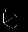
Ex. - Use this UCS for drawing vertical columns.
For our structural example, we will use the "Wide Flange" shape tool.


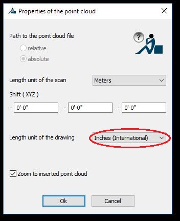
Select the "Wide Flange" tool, and the following dialog appears. In the "Select Data File" you will need to select a data file. We usually use the "Wide Flange" file.


Then select the "Member" size. For this example, a W6X15. Now there is an option to select the "Insert Location" point and select the "Centerline Location" which is either "TOP, CENTER, BOTTOM". Both of these are choices in all steel shapes. The main thing to learn in modeling steel, is that ALL centerlines must touch.


Notice at the top, there is also an option to insert the steel member at a certain "Rotation Angle". Leave that at "0" for now. Then select the "Center Node" for the "Insert Location" and choose "Center" for the "Centerline Location". Finally you can choose "Pick Points" to place the steel. 


You will be prompted to pick your starting point, by left-clicking, then prompted to select your end point, I will enter "15'" and hit my "Enter" key. Notice I am using my Polar Tracking which is usually set to 45 degrees. Also notice I am tracking straight "UP" before I enter the 15'.


Final placement, after the "Enter" key shows the centerline to be in the center of the beam. For your part, try double clicking on the beam and change the three options we had earlier, "Rotation Angle", "Insertion Location", and "Centerline Location". Click "OK"

Double-click again on the member, and select a different "Member" size. Click "OK". 

Double-click again and change the "Select Type" then pick a different "Select Data File". Click "OK".

Notice when you change, all the shapes are placed in reference to the "Centerline Location". 

This is a basic walk-through for using the CADWorx Steel modeling application. There will be some "MIDWAY" walk-throughs that will require this knowledge.

Be Helpful,

Jeremy


Thursday, February 2, 2017

CADWorx Midway - ISOGEN Setup

One of the great features of CADWorx Plant is that it will generate a 2D isometric drawing of a 3D piping model automatically, and quickly. CADWorx will use pre-set STYLES created in I-Configure as a rule book for generating the isometric. For Altura designers, please see the setting locations in our "Helpful Information" file on the network.

These styles are found in an "Isometric Directory". This post will walk you through setting up CADWorx to read to the correct location of the isogen styles.

To use the "Isometric Directory", type LAUNCHICONFIGURE in the command line, or select the icon.


The I-Configure program will start, and you will see this window.


In the left "white space" you may or may not see a folder tree like you see here. If there is no folder tree, that means you are not connected to the "Isometric Directory". To do this, select the green horseshoe icon directly above.


This will pop-up a browse window where you will direct the path to the "Isometric Directory". For Altura designers, see the "Helpful Information" file for this location. When you open the directory folder, select the "ProjectList.xml" file, then select "OPEN".


Now the "white space" will be populated. You can expand the folders and see the styles you will have to choose from when running ISOGEN.

Close the I-Configure window. Your CADWorx is now configured to look here for the styles you may need.

See this post regarding how to "cut" isometrics using ISOGEN.

Please ask if you have questions regarding this walk through.

Be helpful,
-Jeremy


CADWorx Midway - ISOGEN - IGO

In CADWorx, there are two ways move from the model to an isometric. You can use ISOGENOUT (IGO) or ISOGENBATCH (IGB).

ISOGENOUT or IGO
IGO is probably the iso-generator we are most used to. It allows you to select components individually or by line number. Type, "IGO" in the command line, or select the icon.


A dialog box will appear, for you to select the Isogen Style you wish to use. For Altura designers, see the Directory, Project, and Style settings in the "Helpful Information" file on our drive. Do not worry about the File Name, the default is fine. Click "OK".


Follow your command line prompts. You have the option to Select components individually, or by Line number.

IGO - Select Components
This is the default setting, if you simply hit enter, you are then prompted to select the components individually in the model. Notice the blue highlighted section of pipe.


After selecting, type "ENTER" and a Results dialog box will appear. It will tell you if the generation was successful, and where the file is located. Here you can select "Open Plot Files" and the generated drawing will open for you in CADWorx.


At this point, you want to make sure you do a "SAVEAS" in the ISO drawing, and save it to the correct location.

IGO - Line Number Select
Or you can enter "IGO" and choose Line number as a selection route.


You are given two options on how to tell ISOGEN what Line Number you want, either by component...


...where you simply select a component on the line you wish to ISOGEN. This is the default setting. Using it will prompt you to select the component, and then it will proceed with the ISOGEN automatically. Your computer will pause for a moment, then the Results dialog will appear. Note in the command line, the steps it went through once I selected an elbow on the desired line number.


You can also select the Line Number by LIST.


A dialog box will appear with all the line numbers you have available in your model.


Find your line number, or line numbers, you can select multiple line numbers, by holding "CTRL" while you select (left-click) what you want. Then select "OK" and wait.


It will generate isometrics for those number you selected. The Results dialog will appear, and you can open all the generated files and begin scrubbing.

Please see this post for a walk through on ISOGENBATCH.

Feel free to ask if you have questions regarding this post.

Be helpful.
-Jeremy