Use the CADWorx Steel menu to model your structures.
Also, see that your models space is set to "Southwest View" or similar 3D view.
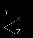
And see that you are drawing in the correct UCS - XY plane. Drawing vertical columns, use UCSNEXT to change your UCS to the proper setup.
 |
| Ex. - Use this UCS for drawing vertical columns. |
For our structural example, we will use the "Wide Flange" shape tool.
Select the "Wide Flange" tool, and the following dialog appears. In the "Select Data File" you will need to select a data file. We usually use the "Wide Flange" file.
Then select the "Member" size. For this example, a W6X15. Now there is an option to select the "Insert Location" point and select the "Centerline Location" which is either "TOP, CENTER, BOTTOM". Both of these are choices in all steel shapes. The main thing to learn in modeling steel, is that ALL centerlines must touch.
Notice at the top, there is also an option to insert the steel member at a certain "Rotation Angle". Leave that at "0" for now. Then select the "Center Node" for the "Insert Location" and choose "Center" for the "Centerline Location". Finally you can choose "Pick Points" to place the steel.
You will be prompted to pick your starting point, by left-clicking, then prompted to select your end point, I will enter "15'" and hit my "Enter" key. Notice I am using my Polar Tracking which is usually set to 45 degrees. Also notice I am tracking straight "UP" before I enter the 15'.
Final placement, after the "Enter" key shows the centerline to be in the center of the beam. For your part, try double clicking on the beam and change the three options we had earlier, "Rotation Angle", "Insertion Location", and "Centerline Location". Click "OK"
Double-click again on the member, and select a different "Member" size. Click "OK".
Double-click again and change the "Select Type" then pick a different "Select Data File". Click "OK".
Notice when you change, all the shapes are placed in reference to the "Centerline Location".
This is a basic walk-through for using the CADWorx Steel modeling application. There will be some "MIDWAY" walk-throughs that will require this knowledge.
Be Helpful,
Jeremy


No comments:
Post a Comment